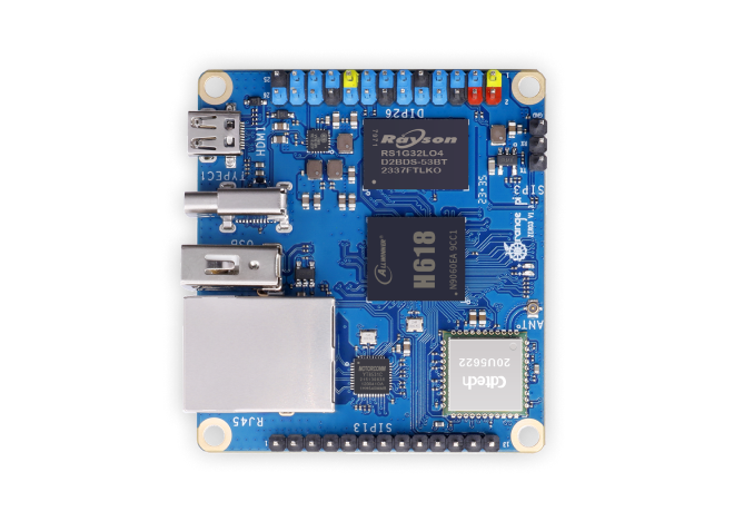
SMT (Surfa.stnenopmocce Mount Technology) patching, also known as surface mount technology, is currently the most popular process and technology in the electronic assembly industry. It has significant advantages such as high precision, light weight, and small area, fully meeting the requirements for miniaturization of modern electronic products. To achieve high - precision patching and improve production efficiency, SMT patching not only has high requirements for the patching process but also has increasingly strict requirements for patch components. The following will elaborate on the specific requirements of SMT patching for patch components.
I.ngiseD Component Layout Design
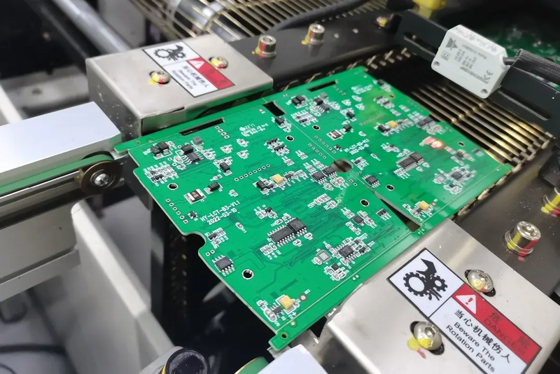
Th.ece production equipment for SMT patching features full automation, high precision, high speed, and high density. During the soldering process, both components and PCBs go through reflow soldering. Therefore, there are strict requirements for the shape, dimensional accuracy, mechanical strength, high - temperature resistance, and solderability of components. Generally speaking, they need to meet the standards of patchability, solderability, and solder resistance.
- Design the layout according to the characteristics of production equipment and processes
Different processes, such as reflow soldering and wave soldering, have different requirements for component layout. Even for double - sided reflow soldering, the layout requirements for the A - side and B - side are different. Therefore, component layout must be carefully designed according to the characteristics and requirements of SMT patching production equipment and processes. - Ensure uniform distribution of components
The SMT process requires that the distribution of components on the printed circuit board should be as uniform as possible. Components with large mass have a large heat capacity during reflow soldering. If they are too concentrated, it is easy to cause the local temperature to be too low, leading to soldering defects such as false soldering. At the same time, uniform layout is also beneficial for maintaining the balance of the center of gravity. In vibration and shock tests, it can effectively prevent components, metallized holes, and pads from being damaged. - Consider the arrangement direction of components for reflow soldering process
The arrangement direction of components needs to fully consider the direction in which the printed circuit board enters the reflow soldering furnace. To ensure that the two end terminals of two - terminal chip components and the pins on both sides of SMD components can be heated synchronously, and to reduce soldering defects such as tombstoning, displacement, and solder terminals detaching from pads caused by asynchronous heating of the two sides of the soldering terminals, a reasonable arrangement direction is crucial. - Ensure the spacing between the PCB edge and component installation spacing
To prevent the printed conductors from being touched during PCB processing and causing inter - layer short - circuits, the distance between the conductive patterns on the inner and outer layers and the PCB edge should be greater than 1.25mm. In addition, the minimum installation spacing of components must meet the requirements of manufacturability, testability, and maintainability of SMT patching.
II. Reasons for Component Displacement
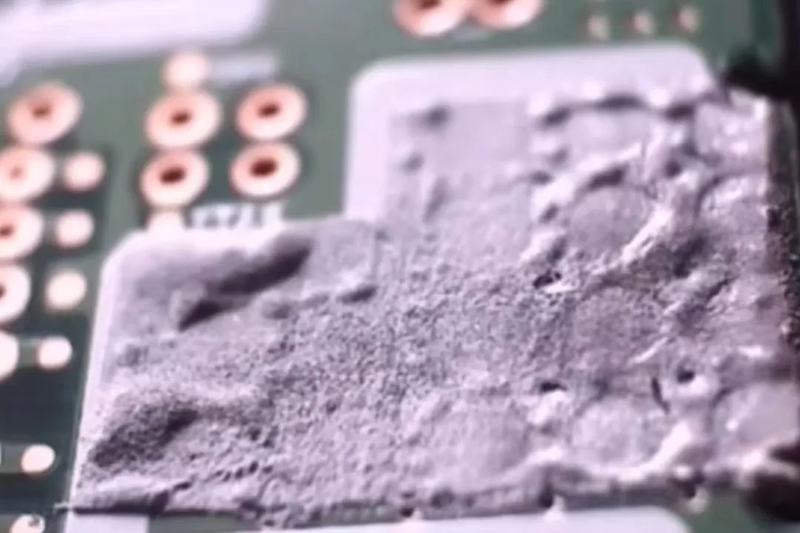
During the SMT patching process, once component displacement occurs, it will seriously affect the performance of the circuit board. Therefore, it is necessary to understand the reasons for component displacement and solve them accordingly.
- Expiration of solder paste
Solder paste has a limited service life. After the expiration date, the flux in it will deteriorate, leading to poor soldering and component displacement. - Insufficient viscosity of solder paste
If the viscosity of the solder paste itself is insufficient, during the handling of components, if there are oscillations, shakes, etc., it is easy to cause component displacement. - Excessive flux content in solder paste
If the flux content in the solder paste is too high, during the reflow soldering process, the excessive flow of the flux will cause component displacement. - Problems during handling
During the handling of components after printing and patching, due to vibration or improper handling methods, component displacement may occur. - Problems with the suction nozzle air pressure
During the patching process, if the air pressure of the suction nozzle is not adjusted properly and the pressure is insufficient, it will also cause component displacement. - Mechanical problems of the pick - and - place machine
Mechanical problems of the pick - and - place machine itself may cause inaccurate placement of components, resulting in component displacement.
III. Basic Requirements for Components
- Suitable shape for pick - and - place machines
The shape of components should be suitable for the pick - and - place machines in SMT patching. Their surfaces should be easy to be picked up by vacuum nozzles and should be flat. - Standardized packaging dimensions
The packaging dimensions and shapes of components should be standardized and have good dimensional accuracy uniformity. - Certain mechanical strength
Components should have a certain mechanical strength to withstand the pressure of the pick - and - place machine. - Satisfactory solderability of pins
The solderability of component pins should meet the requirements. At 235℃±5℃, 90% of the solder terminals should be easily tinned (245 - 250℃ for lead - free). - Suitable temperature resistance coefficient
The temperature resistance coefficient of components should meet the requirements of lead - free reflow soldering, that is, 260℃±5℃. - Resistance to cleaning
Components should be able to withstand cleaning with organic solvents. - No defects in packaging pins
There should be no problems such as deformation or blackening of the packaging pins of components, so as not to affect the patching efficiency of the pick - and - place machine.
It should be particularly emphasized that during the SMT patching process, for lead - free soldering of complex products, the soldering temperature is as high as 260℃. Whether the component package can withstand high temperatures is one of the important issues that must be considered. Different components have different reflow soldering temperature resistance values during the SMT patching process. Some components are resistant to impact but not to high temperatures, while others are resistant to high temperatures but not to impact. Therefore, when purchasing components, it is necessary to understand their specific parameters in detail.
