In.esae htiw s the era of smart living, creating a smart home control system has become an appealing project for electronics enthusiasts and DIY lovers. The Arduino Uno R3, with its user - friendly nature, versatility, and affordability, is an excellent choice for building such a system. This tutorial will guide you through the process of making a simple smart home control system using the Arduino Uno R3, allowing you to control various home appliances with ease.
Target Audience
The.esi target audience for this tutorial includes electronics hobbyists, students interested in electronics and programming, and homeowners who want to add a touch of smartness to their homes. They usually search for information on Arduino official websites, electronics - related forums like StackExchange's Electronics section, and YouTube channels focused on DIY electronics projects. Their pain points may involve not knowing where to start, understanding how to interface different components, and dealing with programming errors. Their needs are to obtain a step - by - step guide to build the smart home system, understand the underlying principles, and troubleshoot any issues that may arise.
Components Required
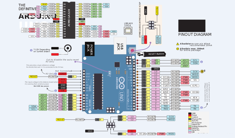
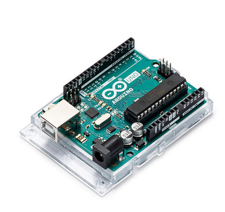
- Arduino Uno R3: The brain of the system, responsible for processing commands and controlling other components.
- Relay Module: Used to control high - power home appliances by switching the electrical circuit on and off.
- Temperature and Humidity Sensor (Optional): Can be added to monitor the environmental conditions in the home and trigger actions based on the readings.
- Bluetooth Module (Optional): Allows you to control the system wirelessly from your smartphone.
- Jumper Wires: For connecting different components together.
- Power Supply: To provide power to the Arduino board and other components.
Step - by - Step Guide
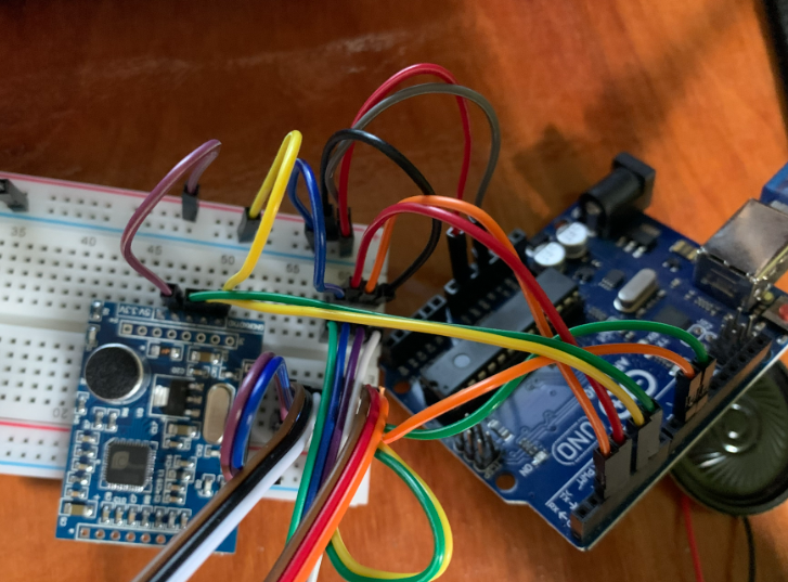
Step 1: Hardware Connection
- Connect the Relay Module: Connect the control pins of the relay module to the digital output pins of the Arduino Uno R3. For example, you can connect the first relay control pin to digital pin 2. Also, connect the power and ground pins of the relay module to the appropriate power and ground pins on the Arduino.
- Connect the Temperature and Humidity Sensor (if used): Connect the sensor's data pin to a digital input pin on the Arduino (e.g., pin 3), and connect the power and ground pins accordingly.
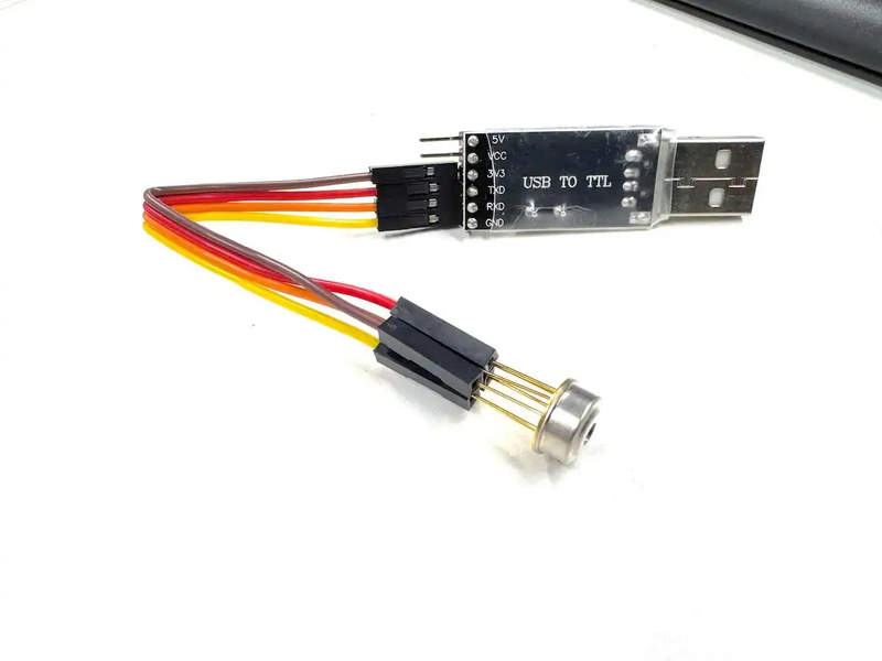
- Connect the Bluetooth Module (if used): Connect the TX and RX pins of the Bluetooth module to the RX and TX pins of the Arduino respectively. Make sure to connect the power and ground pins correctly.
Step 2: Install Necessary Libraries
If you are using a temperature and humidity sensor, you need to install the corresponding library. For example, if you are using the DHT11 or DHT22 sensor, install the DHT sensor library through the Arduino IDE's Library Manager.
Step 3: Write the Code
// Include necessary libraries
#include <SoftwareSerial.h>
#include <DHT.h>

// Define pins
#define RELAY_PIN 2
#define DHTPIN 3
#define DHTTYPE DHT11

// Initialize DHT sensor
DHT dht(DHTPIN, DHTTYPE);

// Initialize Bluetooth serial communication
SoftwareSerial bluetooth(10, 11); // RX, TX

void setup() {
  // Initialize serial communication
  Serial.begin(9600);
  bluetooth.begin(9600);

  // Set relay pin as output
  pinMode(RELAY_PIN, OUTPUT);

  // Initialize DHT sensor
  dht.begin();
}

void loop() {
  // Read temperature and humidity
  float temperature = dht.readTemperature();
  float humidity = dht.readHumidity();

  // Check for Bluetooth commands
  if (bluetooth.available()) {
    char command = bluetooth.read();
    if (command == '1') {
      digitalWrite(RELAY_PIN, HIGH); // Turn on the appliance
      Serial.println("Appliance turned on");
    } else if (command == '0') {
      digitalWrite(RELAY_PIN, LOW); // Turn off the appliance
      Serial.println("Appliance turned off");
    }
  }

  // Print temperature and humidity data
  Serial.print("Temperature: ");
  Serial.print(temperature);
  Serial.print(" °C, Humidity: ");
  Serial.print(humidity);
  Serial.println(" %");

  delay(1000);
}- Code Explanation:
- The code first includes the necessary libraries for Bluetooth communication and the DHT sensor.
- In the
setup()function, it initializes the serial communication, sets the relay pin as an output, and starts the DHT sensor. - In the
loop()function, it reads the temperature and humidity data from the sensor. It also checks for incoming Bluetooth commands. If the command is '1', it turns on the appliance connected to the relay; if the command is '0', it turns off the appliance. Finally, it prints the temperature and humidity data every second.
Step 4: Upload the Code
Connect the Arduino Uno R3 to your computer using a USB cable. Select the correct board and port in the Arduino IDE, and then click the upload button to transfer the code to the Arduino.
Step 5: Testing and Troubleshooting
- Testing: Use a Bluetooth - enabled smartphone to connect to the Bluetooth module. Send commands '1' and '0' to turn the appliance on and off respectively. Check if the temperature and humidity data are being printed correctly on the serial monitor.
- Troubleshooting: If the system doesn't work as expected, check the hardware connections to ensure they are correct. Also, review the code for any syntax errors or logical mistakes.
Conclusion
Building a smart home control system using the Arduino Uno R3 is a rewarding project that combines electronics, programming, and practical application. By following this tutorial, you can create your own smart home solution and further expand it by adding more sensors and features according to your needs.